
← All technical articles · News
Industry Insights
How a Ball Joint Is Made: Forging, Machining, Heat Treatment and the Process Details Buyers Should Audit
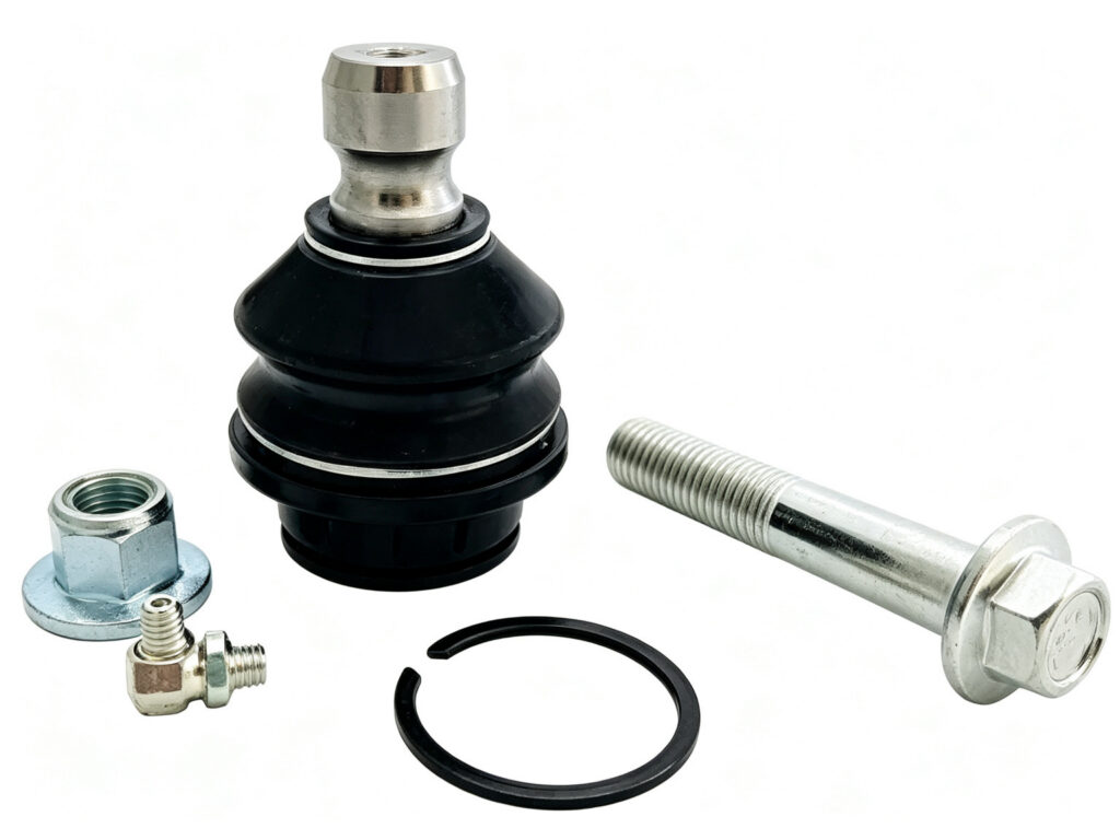
A ball joint rarely fails because it was assembled badly on the last afternoon of the month. It fails because one of five upstream operations drifted outside its window: the forging fold that was never ground out, the socket that came out of the machining cell slightly out of round, the induction coil that left a soft band on the bearing surface, the thread that was cut instead of rolled, or the boot that was crimped with a fold in it. Each of those defects is invisible in a finished part and each of them shows up later as play, noise, a torn boot or a stud that pulls out. This article follows a ball stud from billet to boxed part, gives the numbers that matter at each stage, and lists the questions a buyer can put to a supplier to find out whether those stages are actually controlled. Testing is a separate subject and is covered in our companion guide on factory quality gates; here the focus is on how the part is made.
Quick reference: six process stages and what each one controls
| Stage | What is controlled | What happens when it drifts | What a buyer should ask for |
|---|---|---|---|
| Billet and forging | Steel grade, grain flow through the ball and shank, removal of the decarburised skin | Folds and laps become crack starters; coarse grain lowers fatigue life | Steel grade certificate, forging process sheet, machining allowance sized to remove decarburisation |
| Socket and sphere machining | Spherical radius, roundness, surface roughness, groove position | Contact pressure concentrates, grease film breaks down, rocking play appears early | CMM roundness report and surface roughness value per part number |
| Induction hardening | Case depth and hardness on the bearing surface only; core stays tough | Soft spots wear through quickly; over-hardening produces cracks | Hardness traverse from case to core, plus case-depth measurement per batch |
| Thread forming | Rolled thread with continuous grain and compressive residual stress at the root | Cut threads introduce stress raisers and fail earlier under cyclic load | Process sheet stating rolled thread, thread gauges, runout check |
| Boot, grease and assembly | Boot compound, crimp integrity, grease type and fill, articulation torque | Water and grit enter, grease escapes, joint binds or runs loose | Boot compound and ozone test, grease specification, torque sample record |
| Final verification | Pull-out force, fatigue cycles, salt spray, play | Early separation or corrosion in service, with no paper trail to trace it | Test reports tied to the part number and the production batch |
1. Billet and forging: the grain has to follow the part
A ball stud is a load path with a sphere on one end and a thread on the other, and the fastest way to make that load path weak is to cut it out of a bar. Forging produces a continuous grain flow that follows the contour of the ball and the shank, so the material’s own structure runs along the direction of the bending load rather than across it. A stud machined from solid bar has that flow cut through at every change of section, which is exactly where a bending load concentrates.
The reference construction in the classic patent literature is a cup-shaped housing forged from a medium-carbon steel blank, with SAE 1040 named as a suitable grade, forged to a Brinell hardness of 143–229 before any hardening operation [1]. That hardness range is the soft, tough starting condition: the part is still machinable and still able to take the cold work of later stages, and the hardening comes afterwards and only where it is wanted.
The decarburised skin is a process problem, not a cosmetic one
Heating steel for forging removes carbon from the surface layer. That layer will not respond properly to induction hardening later, because there is less carbon available to form martensite. The patent is explicit that the surface decarburisation produced during forging and coining has to be machined away before the bearing surface can be locally hardened [1]. In practice that means the machining allowance on the ball and socket is not a rounding error; it is sized so that the decarburised skin is removed completely. A supplier who machines to nominal size without accounting for decarburisation can produce a part that looks correct and hardness-checks soft on the surface.
Forging is followed by heat treatment, and the choice of treatment depends on what the part has to do: normalising to refine grain, quench and temper to toughen the body, or a case-hardening route where only the working surface is hardened [3]. For a ball joint housing the last option is the relevant one, because the bearing surface and the mounting body have different jobs.
The alternative to conventional hot forging is cold forging, and the literature is candid about its limits: flashless cold forging of ball studs is energy-intensive, the material’s low plasticity forces multiple stages, and die wear is severe [2]. Cross-wedge rolling has been studied as a way to form the stud more efficiently [2]. None of that makes cold forming wrong; it means the process route has to be chosen against the part’s geometry and volume, and the buyer should know which route produced the part being quoted.
For medium-carbon steels, forging furnaces typically run in the 1100–1250 °C band, adjusted for grade and furnace type; this is an industry practice figure rather than a specification value, and the supplier’s process sheet should carry the actual range. What matters at audit is that the range is written down, monitored and tied to a furnace record, not that it matches a generic number.
2. Machining: roundness before hardness
After forging, the socket is machined to its final spherical form. The patent describes a circular milling cutter used to machine away the decarburised surface and to locate and finish the spherical bearing surface, while also removing the taper left by the forging die [1]. The sequence is deliberate: rough form from the forge, then a machining operation that establishes the true sphere, then hardening on that finished surface. Harden first and machine afterwards, and the hard surface is more likely to crack or grind unevenly.
Roundness is the parameter that decides how the joint wears. A sphere that is slightly oval touches its socket over a narrower band, so contact pressure rises, the grease film breaks down at the edges of that band, and fretting starts. The part will still pass a hand check when new; the symptom appears as rocking play and a knock over small bumps a few thousand kilometres later. Surface roughness works the same way: too rough and the film is interrupted, too smooth and the surface cannot retain grease in the micro-valleys. For suspension ball surfaces, a finished roughness around Ra 0.4–0.8 µm is a common engineering target, though this is an industry practice value that should be confirmed on the drawing rather than treated as a universal rule.
The measurable evidence here is a roundness and roughness report from a coordinate measuring machine or a form tester, tied to the part number. A supplier who can only offer a visual inspection is not controlling the parameter that matters.
3. Induction hardening: a hard shell on a tough core
The bearing surface needs to resist wear; the housing around it needs to resist shock without cracking. Those two requirements pull in opposite directions, which is why the hardening is local rather than through. The patent’s construction forms a precisely localised annular hardened zone at the spherical bearing surface by induction heating followed by a directed quench, leaving the rest of the housing unhardened and tough [1].
The numbers in that reference are useful as a sanity check on any specification a buyer is handed. With an SAE 1040 forging at 143–229 HB, the hardened zone is formed to a depth of 0.010–0.090 inch, or roughly 0.25–2.3 mm, with a preferred range of 0.020–0.080 inch, about 0.5–2.0 mm, and a surface hardness of 40–70 HRC [1]. A specification far outside that band — a case of a few tenths of a millimetre at one end, or a through-hardened section at the other — deserves a question about what the part is expected to do.
What goes wrong inside the coil
Induction hardening is a power-time-quench relationship, and each term has its own failure mode. Too little power or too short a heating time leaves the surface below the austenitising temperature, producing a soft patch that wears through quickly. Too much power or too long a dwell overheats the surface, coarsens the grain and raises the risk of quench cracks. A quench that is late, uneven or contaminated produces inconsistent hardness around the ring, which is worse than a uniformly soft part because the hard and soft zones wear at different rates and the joint develops a tilt.
Hardening also leaves residual stress, so a tempering step follows to relieve it without taking the hardness below the specification. A supplier whose process sheet ends at the quench has skipped a step that shows up as cracking in service or in storage.
The report to ask for is a hardness traverse — measurements from the surface into the core at several points around the ring — not a single Rockwell dot. One dot can be taken anywhere, including on a spot that happened to be correct. A traverse shows whether the case is present, how deep it runs, and whether the transition to the tough core is gradual or abrupt.
4. Threads: rolled, not cut
The thread on a ball stud is a fatigue feature, not just a fastening detail. Every road input passes through the nut and into the thread, and the root of that thread is where the stress concentrates. Rolling forms the thread by displacing material rather than removing it, so the grain flow stays continuous around the root and the surface is cold-worked as it forms. Cutting interrupts the grain exactly at the root and leaves tool marks that act as stress raisers.
The measured difference is not marginal. In comparative data on rolled versus cut threads, rolling produces surface roughness around Sa 0.124 µm, residual compressive stress at the thread root of up to about −247 MPa, and a fatigue strength improvement of roughly 50 percent over cut threads of the same nominal geometry [4]. That is the difference between a stud that survives a pot-holed road for a decade and one that snaps at the thread after a few winters.
At audit, the question is simple and often uncomfortable: does the process sheet specify thread rolling, and does the line have the rolls to prove it? A shop that turns threads on a lathe because it is faster will produce a part that passes a go/no-go gauge and fails in fatigue.
5. Boot, grease and assembly: the parts that decide service life
The boot is the cheapest component on the joint and the one that most often determines how long the joint lasts. Its job is to keep water, salt and grit out and grease in. Once it splits, the bearing surface is being lapped by a contaminated paste and the wear rate rises sharply, which is why boot condition is the first thing to check on any vehicle in service [10][11].
Boot compound selection is a real engineering decision rather than a purchasing shortcut. Chloroprene (CR) covers roughly −40 to +120 °C with moderate oil resistance and good ozone resistance, which suits many suspension joints at a low material cost [9]. EPDM covers roughly −50 to +150 °C with excellent ozone and UV resistance but poor oil and fuel resistance [9]. A joint mounted close to a heat source or exposed to road salt for its whole life is not the same application as one in a mild climate, and the same part number can be specified with different compounds for different markets.
Crimp, fill and torque
Three assembly details are worth asking about because all three fail silently. The first is the crimp or clamp at the boot’s ends: a boot fitted with a fold or a twist will fail within a season even if the compound is correct. The second is grease type and fill volume: too little and the surface runs dry at the extremes of articulation, too much and the boot can be distended and split when the joint swings. The third is articulation torque — the resistance the stud meets when it rotates and swings in the socket. Too high and the joint binds, generating heat and stressing the boot; too low and clearance is already present at the factory.
None of these are visible after the part is boxed. They are controlled by a torque sample record and a grease specification, which is why they belong on the audit list rather than in the “trust the supplier” column.
Where each process defect shows up in the field
The value of mapping process to failure is that a field return can be traced back to a stage instead of being written off as random. A torn boot with clean grease inside points to a crimp or compound problem, not to a bearing problem. A joint with play but an intact boot points to roundness, case depth or preload. A stud that breaks at the thread points to a cut thread or an uncontrolled heat treat at the shank. A joint that seizes within a few thousand kilometres points to insufficient grease, excessive articulation torque or a boot that was fitted dry.
The inspection numbers used in service make the same point from the other direction. Axial spring deflection of the ball pin against its housing should not exceed about 2.0 mm on the joint design referenced by TRW’s technical guidance, measured under load with the suspension loaded [6]. Laboratory work on steering ball joints of 19–21 mm stud diameter uses radial test forces of around ±1000 N and axial forces of around ±400 N, rising to about ±3000 N radial and ±1000 N axial for 22–32 mm studs [5]. Those are test inputs rather than field limits, but they show the load class the hardening and the thread have to survive.
Corrosion is the slow version of the same story. Neutral salt spray testing to ISO 9227 is the standard method for evaluating a coating system’s resistance [7], and test durations in corrosion data sheets run from 96 hours up to 1000 hours depending on the specification being demonstrated [8]. For underbody parts in coastal markets, buyers commonly write 480–720 hours into the drawing for functional surfaces [12]; the honest position is that the number belongs in the specification, because a supplier cannot be held to a duration that was never stated.
What to audit, by buyer type
Independent aftermarket distributors
For a distributor, lot-to-lot consistency matters more than a single impressive test result. Ask for reports tied to the production batch, not a generic type test from three years ago, and ask how the supplier handles a change of forging source, steel mill or boot compound. A process change notification clause is worth more than an extra point of hardness, because the part that fails in year two is usually the one whose boot compound quietly changed.
Tier-1 and OEM programme buyers
On a programme, the process is the product. A PPAP submission should carry the forging process flow, the heat-treat specification with case depth and hardness limits, the thread rolling method, the boot compound with its ozone test, and the control plan for each of those stages. Special characteristics — case depth, thread integrity, articulation torque — should have SPC data, and traceability should run from heat lot to finished part. If the supplier cannot show a hardness traverse, the PPAP is incomplete regardless of what the sample measured.
Fleets and workshops
At the counter, the practical checks are narrower: buy by OE number or a verified interchange, inspect the boot for folds and the crimp for security before fitting, use the specified torque, and align the vehicle afterwards. A correctly made joint installed with a twisted boot will fail like a badly made one, and the workshop will blame the part.
About Hetian
Hetian has manufactured chassis and suspension parts since 1998 from a 160,000 m² facility in Wuhu, China, operating to IATF 16949 with an CNAS-accredited laboratory and more than 100 patents, and supplying customers in over 30 countries. Our ball joint and stabiliser link range is catalogued by OE reference and by platform; the category pages below list the current part numbers.
FAQ
Is a forged ball stud stronger than one machined from bar stock?
Yes, for the same material and section. Forging keeps the grain flow continuous along the ball and shank, while machining cuts through it at every change of section — precisely where bending stress concentrates. The advantage is structural, not cosmetic, and it is one reason a forged and correctly hardened stud can be lighter than a machined equivalent.
What case depth should a ball joint bearing surface have?
The classic reference construction uses 0.25–2.3 mm with a preferred 0.5–2.0 mm and 40–70 HRC on an SAE 1040 forging [1]. Treat those as a sanity band rather than a universal specification: the drawing governs, and the supplier should demonstrate the depth with a traverse rather than a single hardness reading.
Are rolled threads really stronger than cut threads?
In fatigue, yes. Comparative data show roughly 50 percent higher fatigue strength for rolled threads, with compressive residual stress at the root of up to about −247 MPa and a much smoother root surface [4]. The static pull-out strength of the stud may be similar; the difference appears under repeated loading, which is what a suspension joint actually sees.
Why does a new ball joint develop play within a year?
Most often the boot: a fold at the crimp, a compound that hardens in cold weather, or a nick from installation lets contamination in. The next most common causes are a soft case from an out-of-window hardening process and insufficient grease. None of these are visible at delivery, which is why the process records matter as much as the part.
Does the boot material really matter, or is it all black rubber?
It matters. Chloroprene covers about −40 to +120 °C with moderate oil resistance, while EPDM covers about −50 to +150 °C with excellent ozone and UV resistance but poor oil resistance [9]. A joint near a heat source and a joint in a salt-spray environment are different applications, and specifying the wrong compound shortens life regardless of how good the bearing surface is.
Can I tell from the outside whether the heat treatment is correct?
Not reliably. A soft case and a correct case look identical when new; the difference appears as wear rate after several thousand kilometres. The only practical check at receipt is documentation: a hardness traverse and a case-depth measurement tied to the batch. Anything else is guesswork.
What test documents should arrive with a shipment?
At minimum, a pull-out force result, a fatigue test summary, a salt-spray result to ISO 9227 with the duration stated, an articulation torque sample, and a material certificate for the steel lot. The reports should carry the part number and batch, not just a date. Our companion article on factory quality gates explains what each of those tests proves.
Related Guides
- Ball joint factory quality gates: how ball studs are tested before shipment — the test side of the same part, from pull-out to salt spray.
- Ball joint boot cracked? Dust boot damage, inspection and replacement guide — why the boot, not the bearing, usually decides service life.
- Ball joint failure: symptoms, safety risks and replacement — how the process defects described here appear on a vehicle.
- Front suspension rebuild: when to replace control arms, ball joints and bushings — the replacement decision that follows a failed joint.
- Aftermarket control arm quality: a supplier verification checklist — the same audit logic applied to the arm around the joint.
- Product category: ball joints and stabiliser links — current part numbers by platform.
References
[1] Pivot joint housing and ball stud construction with localized induction-hardened bearing zone, US Patent 4,134,701, granted 1979, https://patentimages.storage.googleapis.com/pdfs/US4134701.pdf
[2] Numerical and experimental analysis of a cross wedge rolling process for producing ball studs, Manufacturing engineering study, https://daneshyari.com/article/preview/6694750.pdf
[3] How is ball joint forging done? Process, heating and heat-treatment options, Made-in-China.com factory guide, accessed 16 November 2026, https://www.made-in-china.com/factory/ball%20joint%20forging.html
[4] How the thread manufacturing process becomes the decisive factor in bolt fatigue life, Guangzhou Juxin Development Co., accessed 16 November 2026, https://www.juxinfasteners.com/screws-and-bolts-industries-solutions/thread-manufacturing-process-becomes-decisive-factor-in-bolt.html
[5] Study concerning the ball joint functionality of a vehicle steering system, Annals of the Faculty of Engineering Hunedoara, 2014, https://if.ugal.ro/old/TMB/2014/L10_Anale%202014_Baroiu.pdf
[6] Ball joint technical tips: checking matched bearings and axial spring deflection, TRW Aftermarket, accessed 16 November 2026, https://trwaftermarket.us/pages/tech-tips
[7] ISO 9227:2022 Corrosion tests in artificial atmospheres — Salt spray tests, International Organization for Standardization, https://www.iso.org/obp/ui/fr/#!iso:std:81744:fr
[8] Corrosion tests: salt spray methods and durations (DIN EN ISO 9227 NSS, 5% NaCl, 35 ± 2 °C, 96 h to 1000 h), Nonachem technical data sheet, https://nonachem.com/assets/downloads/63457f67/corrosion-tests.pdf
[9] Rubber bellows, boot and corrugated sleeve: material selection and temperature ranges, Jiaxing Tosun Rubber & Plastic, 16 March 2026, https://www.tosun-rubber.com/news/industry-news/rubber-bellows-boot-corrugated-sleeve-complete-guide.html
[10] How to inspect ball joints for looseness, MOOG technical tip, https://www.moogparts.com/content/dam/marketing/North-America/moog/pdf/tech-tips/How%20to%20Inspect%20Ball%20Joints%20for%20Looseness_MOOG%20Tech%20Tip.pdf
[11] MOT inspection manual: cars and passenger vehicles — section 2, steering (excessive wear or free play in a steering ball joint: major defect), GOV.UK, updated 14 October 2026, https://www.gov.uk/guidance/mot-inspection-manual-for-private-passenger-and-light-commercial-vehicles/2-steering
[12] Corrosion-resistant suspension systems for 4×4 vehicles: salt spray duration guidance for functional surfaces, G·SAI, 18 April 2026, https://gsaishockabsorber.com/corrosion-resistant-suspension-systems-for-4×4-vehicles-in-mexico/
Last updated: Nov 16, 2026 · Reviewed by the Hetian engineering team
